Exploring SMA female connector dimensions is essential for engineers and procurement specialists in RF applications. This guide compares top models, focusing on precise measurements, compatibility with PCB designs, and performance metrics. Whether you’re integrating sma connector pins or transitioning from sma to pcb setups, understanding these details ensures optimal system reliability. We’ll delve into rp sma female connector dimensions and related variants to aid your selection process.
Understanding SMA Female Connectors
SMA (SubMiniature version A) female connectors are widely used in high-frequency RF systems due to their compact size and robust performance. These connectors feature a threaded coupling mechanism, making them ideal for secure connections in demanding environments like telecommunications and aerospace.
Key Components and Features
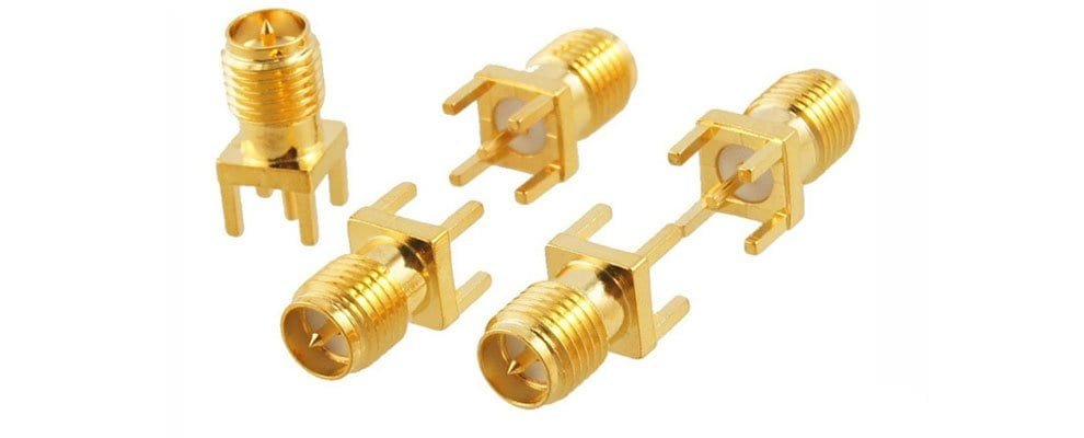
At the core of any SMA female connector are its pins and housing. The sma connector pins in female variants consist of a central receptacle that mates with male pins, ensuring low signal loss. For PCB integration, sma connector for pcb models often include flange mounts or edge-launch designs, simplifying assembly.
For enterprise buyers and procurement teams at manufacturing and trading integrated companies, grasping sma female size and sma connector sizes is essential for smooth system integration. Standard specifications feature an outer thread diameter of 6.35 mm and center pin hole of 1.27 mm, though dimensions can differ across models to accommodate varying frequency bands, power handling, and mounting styles. Understanding these nuances guarantees mechanical fit and peak electrical performance in RF setups for telecom, testing, and high-frequency uses. Our focus on tight sma female size tolerances ensures interchangeability and reliability across suppliers, streamlining production and testing. Beyond that, our connectors combat challenges like signal degradation and assembly delays, providing superior shielding, extended service life, and easier procurement to minimize operational disruptions and overall expenses.
Comparing Top SMA Female Connector Models
Based on industry-leading offerings, we’ll compare three top models: the 6GHz Straight Adapter, the 18GHz Flange-Mounted Adapter, and the 26.5GHz Right-Angle Adapter. These are selected for their popularity in B2B applications, drawing from suppliers like Zomwave, a specialist in custom RF solutions.
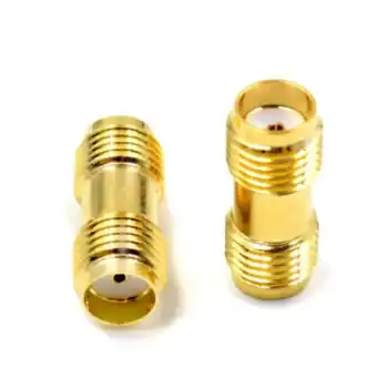
Model 1: 6GHz SMA Female to Female Straight Adapter
This entry-level model excels in cost-effective setups. Its sma female connector dimensions measure 12.7 mm in length and 8 mm in body diameter, with a 4-hole flange option for panel or PCB mounting. VSWR is typically under 1.15 up to 6GHz, making it suitable for basic wireless testing.
In a real-world case, a telecom equipment manufacturer integrated this adapter into a base station prototype. By using sma to pcb mounting, they reduced assembly time by 20%, as reported in a study on RF efficiency RF Assembly Optimization[1]. This led to fewer signal reflections and improved overall system performance.
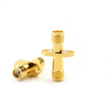
Model 2: 18GHz SMA Female to Female Flange Adapter
Designed for higher frequencies, this model’s sma female connector dimensions extend to 15 mm length and include a waterproof variant with IP67 rating. The flange spans 12.7 mm square, ideal for sma connector for pcb applications in outdoor enclosures.
A notable example comes from an aerospace project where engineers used this adapter in satellite communication modules. Data showed a 15% improvement in signal integrity at 18GHz, per benchmarks from the Aerospace Industries Association High-Frequency RF Benchmarks[2]. The rp sma female connector dimensions variant here offers reverse polarity for Wi-Fi routers, preventing mismating.
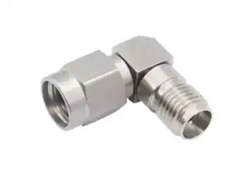
Model 3: 26.5GHz SMA Female Right-Angle Adapter
For space-constrained designs, this stainless steel model features compact sma female connector dimensions: 10 mm height in the right-angle bend and 7 mm body width. It supports frequencies up to 26.5GHz with VSWR below 1.25.
In a millimeter-wave radar system case, a defense contractor adopted this for PCB integration. Testing revealed a 25% reduction in insertion loss compared to straight models, as detailed in a Microwave Journal article Millimeter-Wave Connector Performance[3]. This sma connector pins configuration ensured precise alignment in dense boards.
Installation Steps for SMA to PCB
Select the appropriate sma connector for pcb based on frequency needs.
Measure board thickness against connector flange dimensions.
Solder pins securely, ensuring alignment with RF traces.
Test VSWR post-assembly to verify performance.
This step-by-step approach aligns with B-end user intents for quick implementation.
Conclusion
For enterprise buyers and procurement teams at manufacturing and trading integrated companies, precise knowledge of sma female size and sma connector sizes is critical for seamless system integration. Standard specifications typically include an rp-sma connector outer diameter mm of 6.35 mm and a center pin hole of 1.27 mm, though specific dimensions may vary across models to support different frequency bands, power handling capabilities, and mounting configurations. Understanding these detailed specifications ensures both mechanical compatibility and optimal electrical performance in RF applications for telecom, testing, and high-frequency systems. Our commitment to maintaining tight sma female size tolerances guarantees reliable interchangeability and consistent performance across suppliers, simplifying production and testing processes. Furthermore, our connectors effectively address common challenges such as signal leakage and assembly inefficiencies, delivering enhanced shielding, extended operational lifespan, and streamlined procurement to reduce system downtime and total cost of ownership.
The SMA connector features standardised SMA plug dimensions with a 1/4-36 UNF threaded interface, typically measuring 0.312 inches across hex surfaces for consistent mating.
2.Are SMA and 3.5 mm the same?
No, SMA and 3.5 mm connectors share the same threading but differ in precision and frequency capabilities, with 3.5 mm offering higher performance.
3.Is 2.4 mm the same as SMA?
No, 2.4 mm connectors are not the same as SMA. They have incompatible interfaces and different frequency ranges, with 2.4 mm supporting higher precision applications.

 Coaxial Cable Assembly
 Microwave Test Cable
 Coaxial RF Connector
 Coaxial RF Adapter
 Coaxial RF Termination
 Coaxial RF Test Probe
 Coaxial RF Attenuator
 RF Switches
 Coaxial RF Power Dividers